Welcome to the forum for MobiFlight! Feel free to reach out to the community in case you have questions, issues or just want to share great ideas or details about your latest home cockpit project.
You like MobiFlight? Donate via PayPal and support the MobiFlight development. Thanks!
The community support for MobiFlight has moved exclusively over to our Discord server. Register for free and enjoy more interactive functions like image and video upload, voice chat. More than 7,000 registered users around the world make it a great experience!
See you on our MobiFlight Community Discord server.
A HUGE Thank You to everyone who participated in the forum, especially obviously to Pizman and Stephan who did an outstanding job over so many years providing an incredible service to the MobiFlight community.
The forum is still providing a lot of good content, hence we keep this information accessible.

 CDI Needle Schematics by Jay, on Flickr
 VIDEO0037 by Jay, on Flickr
 From/To Flag Schematics by Jay, on Flickr
 2019-12-26_11-15-17 by Jay, on Flickr
 2019-12-26_11-16-09 by Jay, on Flickr
 2019-12-26_11-16-33 by Jay, on Flickr
 2019-12-26_11-16-58 by Jay, on Flickr
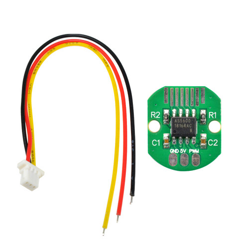
 AS5600 by Jay, on Flickr